
How GIGAFLIGHT Designs for EMI, EMP, and Signal Integrity Across Critical Applications
Why Shielding Matters in Cable Design
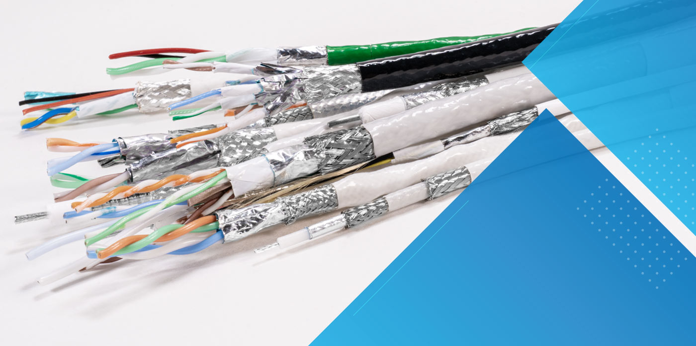
In aerospace, defense, marine, and other sectors, electronic systems operate in electrically complex and often harsh conditions. Avionics, communication systems, RF components, high-speed data networks, and video transmission lines must function reliably despite exposure to electromagnetic interference (EMI), vibration, temperature extremes, and mechanical stress.
Within this context, shielding in electronic cables becomes an important design consideration. Shielding refers to conductive layers incorporated into cable construction that help manage the movement of electromagnetic energy.
When shielding is properly integrated into a cable design and installed within a well-engineered electrical system, it can support signal integrity and reduce the potential for interference between electronic systems.
This paper explains what shielding effectiveness means in practical engineering terms, how shielding is incorporated into cable construction, and how GIGAFLIGHT approaches shielding design across its cable families serving regulated and high-performance industries.
What Shielding Effectiveness Means in Real-World Scenarios
Shielding effectiveness (SE) is commonly used to describe how well a material or cable assembly reduces electromagnetic energy passing through a shielding barrier.
It is typically expressed in decibels (dB), representing the ratio of electromagnetic energy before and after shielding is applied.
In engineering literature, shielding effectiveness is often represented using relationships such as:
SE (dB) = 20 log (E₁ / E₂)
Where: E₁ represents the incident electric field strength, E₂ represents the transmitted electric field strength after shielding.
Shielding effectiveness may also be expressed in terms of power density:
SE (dB) = 10 log (P₁ / P₂)
Where: P₁ represents incident electromagnetic power density, P₂ represents transmitted power density after shielding.
These formulas illustrate how shielding performance may be evaluated in controlled environments. In real-world installations, however, shielding behavior can vary depending on cable construction, grounding methods, routing practices, and the surrounding electrical environment.
Because of these variables, shielding is generally considered one component of overall electromagnetic compatibility (EMC) design rather than a standalone solution.
Interpreting Shielding Levels
Because the decibel scale is logarithmic, relatively small numerical changes can represent significant reductions in electromagnetic energy passing through a shielding barrier.
The following table illustrates how shielding levels are commonly interpreted in general engineering discussions. Actual shielding behavior depends on cable construction, installation practices, grounding methods, and the surrounding electromagnetic environment.
| Approximate Shielding Level | What it Means in Simple Terms | Typical Context |
|---|---|---|
| ~20 dB | Reduces a noticeable portion of electrical noise | Basic Electronic environments |
| ~40 dB | Blocks most everyday interference sources | Many commercial electronics |
| ~60 dB | Significantly limits signal leakage and external noise | Higher-performance communication systems |
| 60 dB+ | Often associated with complex or highly sensitive electronic environments | Aerospace, defense, and specialized platforms |
What Shielding Achieves and Common Misunderstandings
Cable shielding is sometimes assumed to be a universal solution to interference problems. In practice, shielding is one part of a broader strategy that includes grounding, routing, bonding, filtering, and enclosure design.
When incorporated into an appropriate cable design and electrical system, shielding can help:
- Reduce radiated emissions from signal conductors
- Limit susceptibility to external electromagnetic fields
- Support stable signal transmission at higher frequencies
- Reduce coupling between adjacent circuits in complex cable assemblies
However, shielding alone does not guarantee the elimination of interference. Improper termination, inadequate grounding, or system-level design issues can significantly reduce the effectiveness of shielding.
Another common misconception is that adding more shielding layers always improves performance. While additional shielding layers may influence attenuation across certain frequency ranges, they can also increase weight, stiffness, and cost. Effective cable design balances shielding considerations with mechanical and environmental constraints.
Key Factors Influencing Shielding Effectiveness
Shielding performance depends on multiple interacting design elements. It is not determined solely by the presence of a braid or foil layer.
Shielding Material Selection
Table 2 below illustrates the materials used for shielding influence conductivity, corrosion resistance, weight, and mechanical durability.
| Shield Type | General Characteristics | Common Applications |
|---|---|---|
| Foil Shield | Thin conductive layer providing broad coverage | High-frequency data and communication cables |
| Braided Shield | Interwoven metal strands providing flexibility and durability | Applications involving vibration or movement |
| Foil + Braid Combination | Combines high coverage with mechanical strength | Aerospace and other demanding environments |
| Multiple Shield Layers | Additional layers used in complex electrical systems | Dense electronic environments |
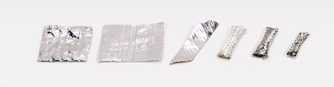
As one can see from the table, foil shields often provide high coverage, while braided shielding offers durability and flexibility. Many cable designs combine multiple shielding layers to support different electrical and mechanical conditions.
Shielding Coverage and Geometry
In braided shields, shielding behavior can be influenced by weave angle, wire diameter, and construction geometry. Coverage percentages often provide a general reference point, but they do not fully define how shielding performs across different frequencies or installation conditions.
Grounding and Termination
Shield termination is one of the most important and frequently overlooked aspects of shielding performance. Improper grounding or poorly terminated shields can introduce discontinuities that reduce shielding effectiveness and create unintended coupling paths. As a result, shielding performance is closely tied to system-level grounding strategies.
Layering Strategy
Multi-layer shielding constructions, such as foil plus braid, are commonly used in high-reliability systems to support shielding behavior across a broader frequency spectrum. Layered shielding may also provide mechanical redundancy in environments subject to vibration and mechanical stress.
Assembly Quality
Even a well-designed cable may underperform if manufacturing processes compromise shielding integrity. Consistent stripping, crimping, soldering, and termination practices help maintain shielding continuity throughout the cable assembly. GIGAFLIGHT operates under ISO 9001:2015 and AS9100:2016 Rev D quality management systems, supporting consistent manufacturing practices for aerospace and defense applications.
Shielding Approaches by Cable Type
Shielding requirements vary depending on signal type, frequency range, mechanical environment, and system architecture. Treating shielding as a standardized feature across all cable categories can lead to suboptimal results:
| Cable Family | Primary Signal Type | Typical Design Considerations |
|---|---|---|
| GIGACore™ | Composite, multi-circuit cables | Internal signal separation and routing efficiency |
| GIGALite™ | RF coaxial transmission | Controlled impedance and continuous shielding geometry |
| GIGABite™ | High-speed Ethernet/Data | Pair geometry and shielding integration |
| GIGAVideo™ | Video transmission | Stable signal transmission and layered shielding |
GIGACore™ Composite Cables
Composite cable assemblies consolidate multiple signal and power circuits into a single engineered cable structure. In these designs, shielding may be applied selectively to help manage both external electromagnetic exposure and internal coupling between adjacent conductors. Design approaches may include individually shielded pairs combined with an overall cable shield depending on system requirements.
GIGALite™ RF Triaxial and Coaxial Designs
In RF applications, shielding continuity is fundamental to maintaining controlled impedance and minimizing signal loss. Coaxial cable designs naturally incorporate a circular shielding structure surrounding the signal conductor. Material selection, braid density, and connector termination all influence how shielding behaves once the cable is integrated into an RF system.
GIGABite™ Shielded Ethernet and High-Speed Data
Modern aerospace and marine platforms increasingly rely on Ethernet-based data networks. Shielded Ethernet cable designs combine balanced conductor geometry with shielding layers intended to help reduce susceptibility to electrical noise in environments where many electronic systems operate in close proximity.
GIGAVideo™ Triaxial and Coaxial Video Transmission
Video transmission systems require consistent signal stability to avoid visual artifacts or interference.
Triaxial and coaxial cable constructions incorporate multiple shielding layers that help support stable signal transmission across complex routing paths and electrically active environments.
Engineering, Testing, and Validation
While shielding effectiveness can be modeled theoretically, real-world electromagnetic behavior is typically evaluated at the system level. In aerospace and defense environments, electromagnetic compatibility expectations are often defined by frameworks such as MIL-STD-461 and RTCA DO-160. Cables are generally evaluated as part of broader equipment or platform testing, where shielding interacts with grounding, routing, enclosure design, and other electrical factors.
GIGAFLIGHT focuses on developing cable constructions that incorporate shielding approaches aligned with demanding operational environments, considering factors such as temperature range, vibration exposure, routing constraints, and electromagnetic density during the design process.
What frequency range must the shielding address?
Different shielding constructions can behave differently across frequency ranges. Understanding the operating frequencies of the system can help determine what type of shielding configuration may be appropriate.
Is the primary concern radiated emissions, susceptibility, or both?
Shielding is often used either to limit signals leaving a cable or to reduce the influence of external electromagnetic energy entering a cable. In many systems, both considerations may be relevant.
What environmental stresses will the cable experience?
Temperature extremes, vibration, moisture, and mechanical routing constraints can influence both cable construction and the durability of shielding layers.
How will the shielding be terminated and grounded within the system?
Shielding effectiveness is closely related to termination and grounding practices. Poor termination or incomplete grounding can reduce the benefits of otherwise well-designed shielding.
How complex is the surrounding electrical environment?
Systems with dense electronics, multiple communication systems, or high-frequency equipment may require more careful consideration of shielding and cable routing.
Are quality management systems in place for consistent manufacturing?
Manufacturing processes and quality control practices can influence the consistency of cable construction, including the integrity of shielding layers.
Does the supplier provide engineering support for application-specific requirements?
Because shielding requirements vary widely across industries and platforms, engineering collaboration can help ensure that cable designs align with system needs. Shielding performance is rarely defined by a single number or specification. Instead, shielding should be considered within the broader context of system architecture, installation practices, and operating conditions.
Why GIGAFLIGHT
GIGAFLIGHT operates within regulated aerospace and defense markets where reliability and compliance are central considerations. The company’s quality certifications — ISO 9001:2015 and AS9100:2016 Rev D — reflect structured manufacturing controls aligned with industry expectations.
Rather than positioning shielding as a generic feature, GIGAFLIGHT considers application requirements when developing cable designs across its composite, RF, Ethernet, and video product families.
This approach allows customers in business aviation, commercial aerospace, marine, defense, and motorsport sectors to select cable constructions that incorporate shielding strategies suited to their operational environments.
Your Next Step in Shielded Cable Design
Shielding effectiveness is not simply a specification on a datasheet. It is a design consideration that influences signal integrity, system integration, and operational reliability.
In aerospace, defense, marine, and motorsport environments, cable shielding must be evaluated alongside factors such as frequency behavior, mechanical durability, environmental exposure, and system grounding practices.
GIGAFLIGHT approaches shielding as part of a broader cable design process, tailoring construction methods across its cable families to support the practical challenges engineers face in demanding electrical environments.
For engineering assistance or to discuss shielding considerations for a specific application, contact the GIGAFLIGHT team.
